Modeling a Typical Home Network
The following mini-project was made as a solution to an assignment for one of my graduate studies courses in the fall of 2020. The project’s Github repo can be found here. A pdf version of this report can be found here.
Model Description
A typical home network only needs a few devices to fulfill a basic standard of service. Most people use the modem/router combination given to them by their ISP as the main access point. Personal devices are required to communicate with one another as well as send and receive communication from the internet. A lot of the variability in the network comes from the speed of the connections to different servers on the internet
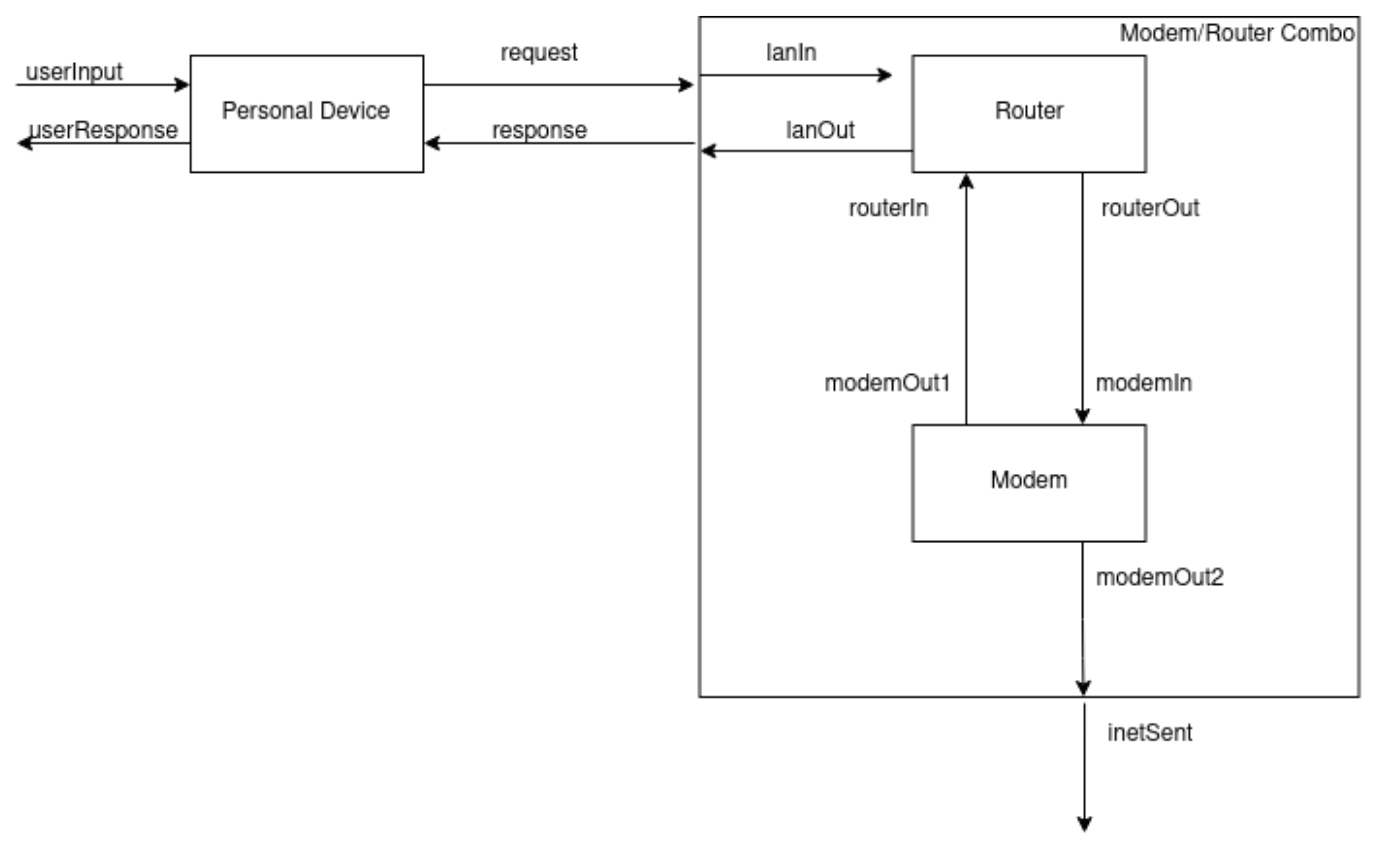
The model I propose consists of two main components: Personal Devices communicate through the Router, and the network is connected to the internet through the Modem. (see Figure 1)

The Personal Device will simulate receiving a userInput (from a file) and sens a request to the Modem/Router Combo. It will wait to receive a response until a predetermined timeout and resend the same request if not received. If a response is received in time, it will output it as a userResponse and continue to the next userInput.
The behavior of the Modem is to receive a request and attempt to send it out to the internet. The Modem will have a randomized wait time between receiving a request and sending the request out to the internet to simulate the variable upload speeds. If the randomized wait time is less than the predetermined timeout, the Modem will send a response as an acknowledgment back to the Router to be sent to the Personal Device.
The role of the Router is to pass on the requests from the Personal Device to the Modem in the Combo as well as the responses from the Modem back to the Personal Device. The Router will have a constant wait time to simulate the processing of the request.
The Typical Home Network has 1 input and 2 outputs. The userInput input controls when a message is sent from the PersonalDevice. The inetSent output shows the time the Modem sends the message to the internet. The userResponse output shows the time that the personal device receives the acknowledgment of its packet from the modem.The Typical Home Network is made up of 2 components: the PersonalDevice, and the Modem/Router Combo. The Modem/Router Combo can be decomposed into 2 subcomponents, one being a Router, and the other a Modem. The PersonalDevice sends messages to the Combo and receives and acknowledgement that the Modem successfully sent the message to the internet.
Formal Specification
The formal specification can be found in the full report here.
Testing Strategy
The atomic models and coupled models will be tested using the “black box” testing method. Test cases are created by adding different combinations of inputs to the test input text files, run the simulation (./TYPICALHOMENETWORK) and check whether the outputs in the output file are as expected.
Testing
PersonalDevice - Atomic
The PersonalDevice has 2 inputs: userInput, and response. The userInput should be a positive integer. It represents a dummy data value to be sent to the internet. If the userInput is negative, the input is ignored. The userInput triggers the PersonalDevice to send messages to the ModemRouterCombo if the PersonalDevice is passive. If the PersonalDevice was already active, the input is ignored. Response is the acknowledgment that should be received from the ModemRouterCombo when the message is successfully sent to the internet. It should have a packetType of 0 and a data value equal to the data last sent. If the acknowledgment is in the correct format and contains the correct data value, the PersonalDevice sends an output of the data on the userResponse port and then passivates, waiting for the next userInput. If the acknowledgment is not received before the PersonalDevice reaches the timeout, it will resend the same message to the ModemRouterCombo.
Router - Atomic
The Router has 2 inputs: lanIn, and routerIn. Both lanIn and routerIn inputs must be messages in the format of {packetType, data&125;. The Router outputs any message it receives on lanIn to routerOut as-is, and any message it receives on routerIn on lanOut as-is. It has a preparation time and cannot accept messages while the current message is being prepared.
ModemRouterCombo - Coupled
ModemRouterCombo is a coupled model that consists of Modem and Router atomic models. All requests from the PersonalDevice go to the ModemRouterCombo. Inside the ModemRouterCombo decisions will be made on waitTime of sending the request out to the internet and whether to send back an acknowledgment or not. The Input of ModemRouterCombo is a Message that includes the packetType and the Data. The outputs are the response (acknowledgment) send to the PersonalDevice, and the Message itself sent to the internet via the inetSent port.
TypicalHomeNetwork (THN) - Top Model
The top model consists of 1 coupled model (ModemRouterCombo) and 1 atomic model (PersonalDevice). The input of the top model should be an integer greater than or equal to 0 which represents a dummy data value to be sent through the modem to the internet. The top model has 2 outputs, userResponse which tells the user that the request was successfully sent from the modem, and inetSent which represents the message sent to the internet. I have created 2 input files for the THN, one of which I will display the outputs of here.
Note: Full results and logs are found in the github repo, and explanations are found in the pdf.
Conclusion
The TypicalHomeNetwork model simulated a network according to our specifications and outputted with the expected results. The models that run in the simulator follow the same formal specification that is given in this document. The data being sent to the internet is modelled as a simple integer dummy value for the purposes of this simulation. The THN simulator works as intended.